|
|
For
participants only. Not for public distribution.
|
 |
Note #43
Khian Hao Lim |
Responsibility of the Sonar System
In our setup, sonars are meant to be used to detect obstacles close by when it is moving slowly. For example, in instances when the vehicle needs to reverse, the SICK laser range finder is not able to detect obstacles behind or next to the vehicle and we would use the sonar readings to determine whether there are obstacles close by. Each sonar should reliably estimate obstacles between 10cm to 3m away. The sonar information is intended to be presented through a SONAR server which replies with the current readings on each of the sonars. We had planned for 16 sonars at first but cut that down to 6.
There is a fundamental problem with sonars -- crosstalk. This and other relevant basics about sonars can be found here. A lot of references are provided there.
Difficulties and Alternatives
Although seemingly an easy task, interfacing water proof automotive grade sonars with a computer proves to be difficulty for many reasons and can be seen in the alternatives we have explored.
- Polaroid provides the transducers and electronics that talk to the transducers. However, the common polaroid ones are generally piezoelectric, non-waterproof and non-automotive grade. These are also not easy to interface. Each transducer talks to a 6500 series ranging module that gives out rs232 output. However, this would mean that we need a serial port for each sonar. Clearly not a good solution.
- A Professor at University of Michigan worked on multi-sonar firing patterns that optimize the number of sonar readings per unit time when using multiple sonars. He made the interfacing electronics available commercially. It works with the 6500 series ranging module and polaroid transducers. So it still remains that the transducers are not automotive grade and not waterproof. However, interfacing with all the sensors is relatively easy because all the ranging data is available through the parallel port and firing coordination has already been handled.
- Automotive grade transducers from Murata are commonly used to build car backup sensors that are commercially available. These typically work between 10cm and 3m, are water proof and easy to install with stick ons or screws hole mounts on their sides. These commercially available sensors typically end up beeping to the driver or displaying ranging distances at a digital display. It means that to interface with them, we would need to build custom hardware that interprets the digital or analog signals and give out serial data. Another disadvantage is the problem that the electronics that interface directly with the transducers cannot be controlled and so firing patterns cannot be coordinated. This however is less of a problem since we could possibly place the transducers facing different directions. Singtech makes some of these reversing sensors and has in fact offered to give us schematics and part layouts on their electronics for us to interpret the digital ranging signal that goes to the digital displays.
- Expensive Massasonic sonars that are hard to mount.
- Devantech produces good sonars systems for hobby robotic uses. They are available in the united states at Acroname. The SRF08 range finder works quite well between 3cm and 6m. The transducers on them however are not water proof and not automotive grade. They talk I2C but there are I2C-to-RS232 converters commercially available. On the same I2C bus, up to 16 SRF08 units can be connected. Some suppliers include Emicros and MCC which also supplies good I2C cables and distribution boards. The transducers on the SRF08 are made by Prowave, a Taiwanese company, that also makes waterproof ones. We wanted to experiment with the waterproof ones instead.
Choice and Problems
In the end, I opted for solution 5. We have in stock 2 functional I2C-to-RS232 converters from Emicros, 7 functional SRF08 units from Devantech, a 7 port I2C bus distribution board from MCC and some special I2C cables from MCC (the distribution board needs special connectors).
I did not take long to get each sonar unit to talk through the I2C-to-RS232 converters. The distance estimation obtained is surprisely good and good to centimeter accuracy.
I then tried changing the transducers on the SRF08 from their stock 400ET180 (transmitter) and 400ER180 (receiver) with the waterproof 400ET250 and 400ER250 from prowave. After much experimentation, it seems with the new transducers, the distance estimation is good only at short distances. At longer distances, they are totally wrong. I also tried experimenting with Murata transducers from reversing parking sensors. That did not work at all. In the end, we are left with using the SRF08 with their native non-waterproof transducers.
It also turns out that I2C signals from the SRF08 units are very sensitive to electrical noise. I tried using 15 yard long shielded cables between the I2C-to-RS232 converters and the SRF08 units. That failed to work. Cutting the cables down to 8 yards or less seemed to work. In the end, I opted to use the distribution board and the special I2C cables from MCC.
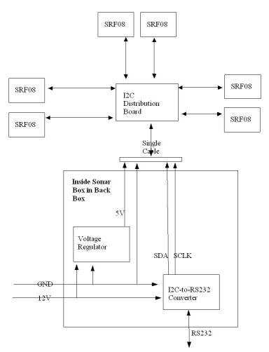
Hardware Implementation
The schematic is shown below. The I2C-to-RS232 converter takes 12V while the SRF08 units take 5V, thus the use of the voltage regulator below. The single I2C cable (with the MCC connector) leaves the sonar box and connects to the MCC I2C distribution board just outside the Back Box. Then each SRF08 is connected to this distribution board via an 8 feet I2C cable.
Software Implementation
The software can be found in the Overbot CVS source tree at sandbox/gc/src/qnx/drivers/sonars/.
The program man page can be found at sandbox/gc/doc/manuals/.
Documentation for the I2C-to-RS232 converter can be found here while the documentation for the SRF08 can be found here.
To communicate with each of the SRF08, the address of each one has to be set differently. Currently, they have been set to 0, 1, ... 5.
The following (as found in main.cc) can be used to change the I2C addresses of the SRF08. Fresh out of the factory, their default number is 0. For example, the following snippet changes the address of the unit currently at address 5 to address 1.
srf08_init(dev);
srf08_select_unit(SRF08_UNIT_5);
srf08_change_i2c_address(SRF08_UNIT_1);
Currently, the software continuously fires and polls each sonar in turn for range estimations. An example of how to do a ping is:
int dist = srf08_ping(SRF08_UNIT_0);
This currently is the simplest possible way to ensure no crosstalk. But through experiment, it seems that this slow process takes 1 second to cycle through all 6 sonars and thus the update rate of each reading is 1hz.
Due to the slow microcontroller on board the I2C-to-RS232 converter, care must be taken in writting the serial interfacing code. The software right now will wait for each expected reply from the converter before sending the next string of commands to prevent overrunning the slow microcontroller.
The I2C-to-RS232 converter has a baud rate setting (currently factory defaulted to 9600) that can be tweaked and experimented with. I refer you to the I2C-to-RS232 converter documentation.
Changes Needed to Add More Sensors
Because the I2C distribution board can be stacked, additional SRF08 can be added by:
- Obtaining new SRF08 units from Acroname, new 8 feet I2C cables from MCC and a new I2C distribution board.
- Stacking the new I2C distribution board on the current one.
- Connecting the new SRF08 units and programming their new addresses
- Modifying the software and add them to the list of addresses to be pinged.
Current Status and Work Needed
- The software is still not acting as a server right now. It only prints out the range values. However, this change should be quite simple.
- The sonars are not mounted yet. Conformal coating or Silicone coating should be sprayed onto the SRF08 units and they should be screwed and mounted down on the vehicle sides. The coatings can be found in the Overbot office.
On Hindsight
It might be much easier (both for mounting and programming) to have gone with option 2 or 3 instead.