|
|
For
participants only. Not for public distribution.
|
Note #26
John Nagle |
The emergency stop system and how it works
 |
|
Preliminary
- see CVS server for actual schematic.
|
Operation
Normal operation
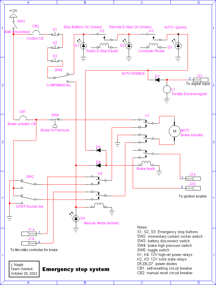
Before the chassis computer can take control of the vehicle, SW3 (the battery disconnect switch) must be on, all three big emergency stop buttons must be released, and SW5, the COMP/MANUAL switch, must be in the COMP position. Green light D1 will then come on.
Next, the radio emergency stop must be enabled, which will close relay K2 and turn on green light D2.
Finally, the chassis computer must activate a digital output which closes relay K3 and turns on green light D3, the "AUTO" light.
This energizes the AUTO ENABLE line, which applies power to the throttle electromagnet L1, enabling computer control of the throttle. Relay K1 is energized, which connects the brake actuator to the servomotor controller and enables the vehicle ignition. A signal is also provided via J2C to inform the chassis computer that control has been enabled. The chassis computer can then operate brakes and ignition.
Emergency stop operation
The emergency stop system does three things: it cuts the throttle, turns off the engine ignition, and applies the brakes.
Three different inputs trigger the emergency stop system: the big red buttons on the vehicle, the remote E-stop, and the chassis computer.
When the emergency stop system is triggered, relay K1 drops out. This connects the vehicle battery directly to the brake actuator via circuit breaker CB1 (an automotive self-resetting circuit breaker) and pressure switch SW4. The actuator will be driven until pressure switch SW4 opens. At this point, the brakes should be locked.
Relay K1 also opens the ignition circuit to stop the engine.
When AUTO ENABLE deenergizes, the electromagnet in the throttle actuator is deeenergized, dropping the throttle to idle.
Manual operation
With SW5 in the COMP/MANUAL position, the brakes can be released and the vehicle driven manually. To operate the vehicle without the computers involved, the SW3 (the battery disconnect) must be ON, all three emergency stop buttons must be released, and SW5 must be in MANUAL. Amber light D4 will then illuminate and relay K4 will energize. The brake actuator can then be released, or applied, using rocker switch SW2 (which is momentary-contact, although not so drawn).
In manual mode, the throttle electromagnet is not energized, so the computers cannot activate the throttle. The throttle pedal will still work.
The COMP/MANUAL switch and rocker switch arrangement is similar to the one we already have for steering, and can be placed and marked similarly on the dashboard. However, we are required by DARPA to provide instructions for emergency brake release for towing, so we will need to mark and placard those controls.
Parked operation
When the vehicle is parked, this system will keep pressure on the brakes, unless the brakes are manually released and the battery disconnect switch then turned off. This may, over time, cause brake leakage, causing the pressure to drop and SW4 to close, which will reapply the brakes. If the brake cylinder bottoms out, the actuator will stall (its limit switch is not used here), then overcurrent, and CB1 will cycle on and off until the battery is drained.
Leaving the COMP/MANUAL switch in MANUAL energizes relay K4 and light D4, which consumes some battery power.
So the vehicle is best left parked with SW3, the battery disconnect switch, off.
Failure analysis
The key components required to operate the brake are the brake actuator, relay K1, the brake pressure switch, and circuit breaker CB1. None of these are redundant. We need to determine whether this is adequate. K1 activates the brake on dropout, so it fails into the safe condition. K1 should be a high-quality relay with silver contacts, because it handles considerable power.
The pressure switch is a concern. If the pressure switch is not sufficiently reliable, we could omit it entirely, drive the brake actuator until it stalls, and let circuit breaker CB1 cycle on and off to limit the power to the actuator. This will drain the battery, but should work.
There is some redundancy in that the throttle actuator electromagnet is energized directly by the AUTO ENABLE line, which is independent of the above components.
