|
|
For
participants only. Not for public distribution.
|
 |
Note #12
John Nagle |
Laser rangefinders, and how to use them for automatic driving.
What's available
 |
SICK LMS 221 laser rangefinder A time-of-flight rangefinder popular in autonomous vehicle work. Used on CMU NavLab 11. Range 1..45 meters. Line scanner; sweeps 180 degrees with resolution of 0.25 degree. Typical range error +- 35cm at 4..20 meters range. Made in Germany. Scanning is done with a 4-sided rotating prism. A 90 degree scan version is available, with an 8-sided prism. |
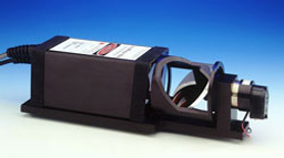 |
Acuity AccuRange 4000 laser rangefinder Another time-of-flight rangefinder. Range 15 meters. Line scanner; sweeps 360 degrees at approximate 2000 RPM, for about 1500 points per revolution, yielding an angular resolution of 0.25 degree. 0.1 inch accuracy. 0.02 inch short-term repeatability. 50KHz sample rate. Made in California. |
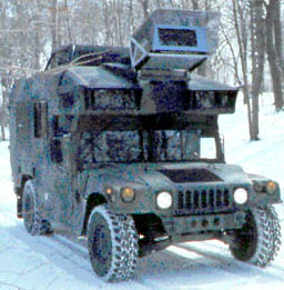 |
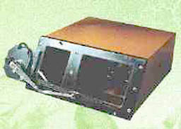
ERIM laser rangefinder A two-axis scanner from the late 1980s. The scanner is the bulky object atop the vehicle, CMU NavLab #2. This device was used on the first vehicle to drive offroad successfully. This scanner is no longer manufactured. It was made in Michigan, by the Environmental Research Institute of Michigan. |
 |
Nordlynx gated laser camera system This is the future - a true depth imager with no moving parts. A laser pulse goes out, and the imager is gated so as to accept light only during the gating period. Thus, only objects within the range limits are visible. These devices are used to see through fog. Field of view 30 degrees in two axes, range 150 to 350m, range resolution (unfortunately) 1 meter. Made in Sweden. Still very expensive, about US$30,000. |
The first two devices scan a line, not an area. Area scanners like the ERIM, with two moving mirrors, have been built and used, but are bulky and fragile. The Nordlynx approach is where the technology is going, but they can't gate the imager fast enough yet.
There's a good analysis from CMU of what's needed in a laser rangefinder. A key point from that paper are that the rangefinder must collect most of its pixels from areas of interest, i.e. the ground ahead of the vehicle. Both of the line sensors above have inefficient fields of view for our application. The ERIM unit didn't have enough resolution.
What we need
How far ahead do we need to sense?
The most difficult sensing problem we face is safely driving at a reasonably high speed on terrain that is mostly flat, but might contain surprises. We thus need good information out to at least our stopping distance, and preferably somewhat further.
A traditional table of stopping distances looks as follows:
|
SPEED |
THINKING DISTANCE |
BRAKING DISTANCE |
OVERALL STOPPING DISTANCE |
|
20 mph |
20 ft. (6 m) |
20 ft. (6 m) |
40 ft. (12 m) |
|
30 mph |
30 ft. (9 m) |
45 ft. (14 m) |
75 ft. (23 m) |
|
40 mph |
40 ft. (12 m) |
80 ft. (24 m) |
120 ft. (36 m) |
|
50 mph |
50 ft. (15 m) |
125ft. (38 m) |
175 ft. (53 m) |
|
60 mph |
60 ft. (18 m) |
180 ft. (55 m) |
240 ft. (73 m) |
|
70 mph |
70 ft. (21 m) |
245 ft. (75 m) |
315 ft. (96 m) |
These are for pavement, and may be optimistic for dirt surfaces. The "thinking distance" represents human reaction time. The stopping distance here is for the maximum deceleration the vehicle can manage, so these represent emergency stop values, not normal driving. These numbers may thus be inaccurate, but are starting points for preliminary design.
We will assume for now that we need to see out 40-50 meters.
What resolution do we need?
The CMU offroad driving work used a 15cm cell, and at least 5 range measurements had to fall into a cell for it to be considered valid. However, out near our range limits we're using this data mostly to insure that where we intend to drive is more or less flat. So we could probably get by with a 1 meter cell, with the five measurements used only to compute flatness. As long as we're sensing relatively flat terrain, big cells should work. When the terrain is rougher, we'll have to slow down anyway, and can use smaller cells sensed at shorter range.
We don't even really need to know where in the cell the measurement is; at long range, all we care about is flatness. So we need only enough angular precision to decide which cell a range measurement hit. We care much more about relative accuracy between data points for the same cell and adjacent cells than absolute accuracy.
[More calculations to follow]
The obvious approach, and why it won't work.
The obvious approach using the available hardware is to take a wide-angle line-scanning rangefinder like either of those above, mount it up high, tilt it slightly downwards, and collect a profile of the ground as the vehicle moves forward. The scanning direction is thus horizontal, or across the track of the vehicle. We might mount the rangefinder on a tilt mount, so that we can adjust the range at which the scan line hits the ground.
[This could use a picture]
In a benign environment, like an indoor lab, good results have been obtained with that approach. But bouncing around the desert, there will be problems. Big problems.
First, we'd have to stabilize the rangefinder mechanically. That's not impossible; tanks have had gyro-stabilized guns for decades, and helicopters routinely carry gyro-stabliized cameras. But it's mechanically complex and expensive. Because we're comparing heights measured from successive scans, we must maintain the scanner angle within a very tight tolerance. We need very high precision between successive scans just to detect flat surfaces.
Second, that approach to scanning scans each bit of ground exactly once. Any data point missed is never filled in by later data. We can't correct for data holes caused by vehicle and scanner movement even if we know the details of the motion. In addition, scanning is usually at near-maximum range, so the data quality will be marginal.
Third, most of the scanning points are wasted. The fields of view of the devices are far too large, and much of the data collected will be irrelevant. Worse, the data densities in the areas of interest are too low.
This seems to be a major reason why autonomous vehicle work is stuck.
A specialized scanner
The 1994 CMU paper on scanner design mentioned above points out that the field of view needs to be aligned with the needs of the problem. That paper suggests a scanner with two moving mirrors, like the old ERIM scanner.
What we need is a scanner mechanically similar to the SICK unit, but with a different prism. As noted, a 4-sided prism yields a 180 degree field of view, and an 8 sided prism yields a 90 degree field of view. A 24-sided prism would yield a 30 degree field of view. With the prism's rotational axis horizontal, we would scan a field of view from the horizon down to -30 degrees, which, if the scanner is atop the vehicle cab, is probably about where the beam hits the hood.
 |
Scanner with 24-face mirror wheel Scans a 30 degree vertical fan. One moving part. |
 |
Scanner field of view - vertical From the horizon, down to the hood. |
Such a scanner would just scan the same vertical line over and over again. We can do better. We can use a specialized prism, with slightly different face angles for each face, so that, instead of scanning on one line, it scans a fan of 24 different vertical lines on each rotation. We now have a 2-axis scanner with only one moving mirror. This concept is similar to the scanning mirrors used in supermarket checkout scanners, which get multiple scan line directions from one multifaceted mirror.
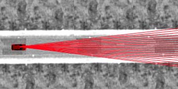 |
Scanner field of view - horizontal 24 scan lines.
Enough to see if the road ahead is flat. |
If we design the prism to scan 24 lines across 4x the vehicle width (say 10 meters) at 50 meters range, we get about 2 samples per meter, or one every 42cm, which is adequate density at that range. We'll be able to see the full width of a 2-lane road, if it's straight. Assuming a modest 1200 RPM mirror speed, we'll get all 24 line scans 20 times a second. With a data rate of 50,000 samples per second, we get 2500 points per mirror revolution, or 104 pixels in each scan line. So our resolution is 24 x 104. At maximum range, we put four depth measurements in each 1 meter cell (see Note #8, "Mapping near the vehicle" for the mapping approach being assumed) every 50 milliseconds. This should be adequate. Note that we keep putting measurements into the same cells on every scan, so small objects missed on one scan probably get picked up on later scans.
If we reduce the data properly, we can detect flat areas without having to precision stabilize the scanner. We need to vibration-isolate the scanner sufficiently that the error from vibration in one line scan (about 2ms) is insignificant, and in one rev (50ms) is small. This is much easier to do than maintaining registration between successive scan lines as the vehicle moves. Remember, all we need for each large 1 meter map cell is the variance in the height and the relative height with respect to adjacent cells. Closer in, the resolution gets better, although because of the narrow field of view, we're not seeing much terrain. Closer than 13 meters, we can't see a space the width of the vehicle.
It's tunnel vision, of course. This device's field of view is about 12 degrees wide horizontally. We'll need a separate sensor system, with more field of view and less range, for our shorter-range navigational problems. All this solves is the "is the road ahead flat" problem, and that only for straight roads. That's enough to let us go fast, most of the time, in the desert.
This looks like a way to break through the major obstacle to fast autonomous offroad driving.
Variations on this theme
We can also use this approach for a near-field scanner. For that application, we'd want a wider field of view. A vertical-axis prism with 8 faces gives us a 90 degree field of view and eight scan lines. Tilting the mirror faces to give us a 30 degree vertical field of view, with a scan line every 4 degrees, gives us our first two scan lines 10cm apart in front of the vehicle. Assuming equally spaced mirror face angles, the scan lines become further apart at greater distances from the vehicle. So we get enough resolution near the vehicle to get started, and once moving, the movement fills in the blanks.
[Need picture of this geometry].
We could increase the resolution in the direction perpendicular to mirror rotation by vibrating the scanner slightly, so that the scan lines move. This is probably not worth the trouble. We'll get enough vibration from vehicle motion that we're unlikely to miss any significant terrain features because they happen to fall entirely between two scan lines.